|
<< Click to Display Table of Contents >> Wellbore and Flowline |
  
|
|
<< Click to Display Table of Contents >> Wellbore and Flowline |
|
Wellbore and Flowline

Wellbore Segments |
See discussion below. |
Deviation survey data can be cut and pasted into the survey panel. Once this data exists, all panels that use this type of data will automatically synchronize as the data is entered/changed. |
|
Severe bottlenecks in the system such as junk in the tubing, severe scale, pinched pipe, or a designed downhole choke are entered in this panel. Normal wellbore jewelry should not be modeled since the pressure effects are immaterial, while the computational overhead is not. |
|
The correlation advisor helps select which hydraulics model is most appropriate for your case. The correlations topic displays a detailed description of each correlation. |
|
These tables show typical pipe sizes for easy access to wellbore tubular tables. |
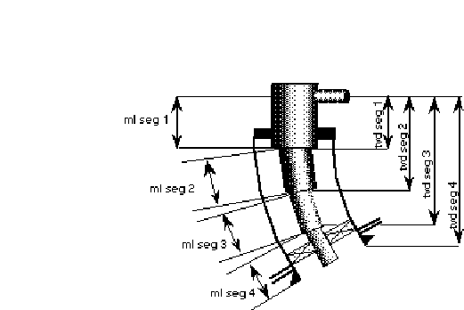
The following items may be edited on the WellBore Geometry Panel:
The WellBore Geometry is input as individual segments used to describe the well geometry starting at the wellhead and ending at the bottom of the hole.
WELL GEOMETRY OPTIONS:
Measured Depth vs. True Vertical Depth
Measured Depth vs. Angle
True Vertical Depth vs. Angle
DEVIATION SURVEY TAB:
FLOW AREA OPTIONS:
Tubular Flow: (Select Tubing I.D.): The flow is through the tubing.
Annular Flow: (Select Tubing O.D. and Casing I.D.): The flow is through the annulus.
TUBING INSIDE DIAMETER (in): The inside diameter of the tubing. By selecting the dimension button on the dialog box a table of the standard tubing and casing O.D.'s and I.D.'s are displayed.
TUBING OUTSIDE DIAMETER (in): The outside diameter of the tubing.
CASING INSIDE DIAMETER (in): The inside diameter of the casing. This is ONLY required or used in the Annular flow case. Do not enter or concern yourself with this number under normal flow conditions.
MEASURED DEPTH (ft): The CUMULATIVE length from the wellhead to the point of interest along the curvature of the well. This is also the wireline depth and the driller's depth. The measured depth impacts the friction pressure.
TRUE VERTICAL DEPTH (ft): The net change in elevation below the wellhead. This is obtained from gyro surveys and reflects the depth of the well if it was a straight, vertical hole. The true vertical depth impacts the hydrostatic pressure.
ANGLE (degrees): The deviation angle measured from straight down. A kick-off-point at 2000 ft with 2 degrees /100 ft build angle to 2200 ft MD would be entered as 2000 @ 0 degrees, 2100 @ 2 degrees, 2200@ 4 degrees, etc.
SEGMENT TEMPERATURE (F): Temperature at the end or bottom of each tubing segment. The program uses the wellhead and bottomhole temperature and calculates a linear temperature gradient. However, this option can be used to specify a nonlinear temperature profile in the well by specifying additional tubing segments and temperatures.
TUBING ROUGHNESS (in): This is the absolute roughness, in inches, of the pipe segment under consideration. It is used to calculate the friction factor. The Crane handbook (technical paper 410) is a good source of pipe roughness data. Here appear Recommended Values.