|
<< Click to Display Table of Contents >> Wellbore Restrictions |
  
|
|
<< Click to Display Table of Contents >> Wellbore Restrictions |
|
Wellbore Restrictions
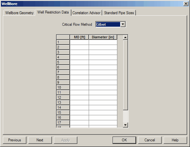
This feature is best used for identifying severe bottlenecks in the system such as junk in the tubing, severe scale, pinched pipe, or a designed downhole choke. IT IS NOT RECOMMENDED (OR NECESSARY) TO INCLUDE MINOR RESTRICTIONS LIKE TUBING NIPPLES, SSSVs, AND OTHER TUBING HARDWARE. If designed properly, these should never create a pressure drop significant enough to impact the overall tubing hydraulics under producing conditions and will just complicate the analysis with one of the least predictable mechanisms in the system (subcritical two phase flow).
RESTRICTION I.D. (in): The restriction I.D. is used to calculate sonic and subsonic two phase pressure drop across a sharp faced orifice. There is no length term in the method since the pressure drop exists as a shock wave. If flow is critical, one of the four critical flow correlations is used to calculate the pressure drop (Gilbert is recommended). If flow is subcritical, a multiphase subcritical flow correlation is used.
For WELLBORE RESTRICTIONS:
MEASURED DISTANCE FROM WELLHEAD (ft): The distance from the restriction to the wellhead.
For FLOWLINE RESTRICTIONS:
MEASURED DISTANCE FROM SEPARATOR (ft): The distance from the restriction to the separator.