|
<< Click to Display Table of Contents >> Gas Lift Valve Design |
  
|
|
<< Click to Display Table of Contents >> Gas Lift Valve Design |
|
For a tutorial on this subject, visit Gas Lift Valve Design Tutorial.
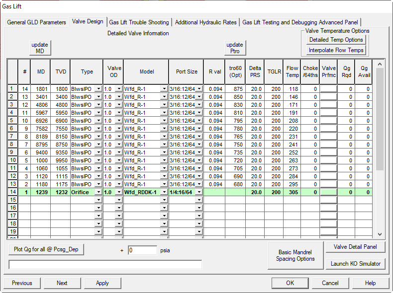
The following items may be edited on the VALVE DESIGN Panel:
TVD and MD (ft): True Vertical Depth and Measured Depth of each gas lift mandrel in the well. If the TVD is modified, clicking the UPDATE MD button will calculate the corresponding MD from the Wellbore Geometry deviation information on the previous panel.
VALVE TYPE: Three types of valves may be selected, Bellows, Orifice, or Dummy. To prevent calculation errors either Bellows or Orifice must be selected in the top row. If there are dummy valves above the first live valve, delete those rows from this panel.
MANUFACTURER: Several gas lift valve manufacturers are in the drop down list, if the manufacturer of the valve you have is not represented, select Camco.
VALVE OD: 1” OD or 1-1/2” OD can be selected.
PORT SIZE: Port sizes from 1/8” diameter to ¾” diameter can be selected. All port sizes are not physically available for all gas lift valves. Check port size availability for your valve size and manufacturer. Adjust port sizes as you run the calculation and check that the quantity of gas supplied by the valve is greater than gas required. For the top valve always select the smallest port size that will pass the required volume of lift gas because it conserves casing pressure to be used to lift the well at the deepest possible depth.
R VALUE: This is the Av/Ab ratio (area of port diameter to area of bellows diameter) for the particular valve parameters that have been selected. The R value field is automatically populated when valid valve parameters have been selected. Optional R values may be typed in if the program values do not match those of your gas lift valves. If an optional R-value is chosen, TUALP flow method may not function properly.
TRO60: This is the calculated Test Rack Opening Pressure at 60 deg F. After a calculation has been run by clicking the apply button at the bottom of the panel (same as the APPLY BUTTON on the General panel), the displayed TROs can be updated to the calculated values by clicking the UPDATE TRO button. If a trouble-shooting run is being calculated, the TROs for the valves actually installed in the well must be typed into this field.
DELTA PRESSURE: The program calculates the surface closing pressure of the top gas lift valve and then applies this DELTA PRESSURE to calculate the surface closing pressure of the next valve down hole. In other words, this delta pressure controls the pressure drops required to close unloading valves as you move down hole. Delta pressures sufficient to prevent valve interference should be used. The sum of all of the DELTA PRESSURES is subtracted from the SURFACE CLOSING PRESSURE (Psc) of the top valve to calculate the maximum SURFACE CASING PRESSURE. If an orifice valve is used as the operating valve, no DELTA PRESSURE is required for the valve above the orifice valve because the orifice valve has no surface closing pressure to calculate. Designers may elect to use different delta pressures when working with gas lifts systems that have different supply pressures. For example, the designer might select a delta pressure of 10 psig for a system pressure of 800 psig, 20 psig for a 1400 psig system, or 50 psig for an 1800 psig system.
GLR: This is the TGLR (total gas liquid ratio) required to move the lift point from this unloading valve down hole to the next unloading valve. The GAS LIFT SIMULATOR UTILITY may be used to help define these values. To move the lift point down to the next valve, a pressure must be created in the tubing at the current valve depth that is equal to or less than the TRANSFER PRESSURE. The transfer pressure is graphically defined by the intersection of the UNLOADING GRADIENT line and the current valve depth line.
FLOWING TEMPERATURE: The flowing temperature in the tubing at the valve depth during objective operating conditions. This temperature is used in the trouble shooting panel calculations, but in this program version it is not used to calculate TRO. A straight-line interpolation can be performed by clicking the interpolate button above the column. The surface flowing temperature from the GAS LIFT DESIGN, GENERAL panel is used in the interpolation. If actual flowing temperatures from a survey are available, they should be typed in the appropriate fields.
STATIC TEMPERATURE: In this program version these temperatures are used to calculate TRO. A straight-line interpolation can be done by clicking the interpolate button at the top of the column. The KICKOFF WELLHEAD TEMPERATURE is used in the interpolation. Actual well temperatures from a survey, if available, should be typed into the input fields
USE: In a future program version this column will be used to select the temperature column to be used to calculate TRO. The current program version uses the STATIC TEMPERATURE column for TRO calculations.
Plot Qg for all methods. This button will create or update a plot showing the performance of the selected valve at the casing pressure indicated and a range of tubing pressures. The following shows a sample of all valves with the selected method.
Thornhill Craver Method VPC Method
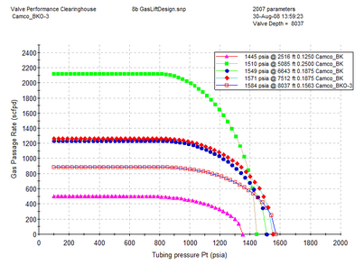
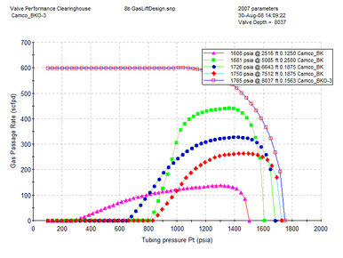
Winkler Method
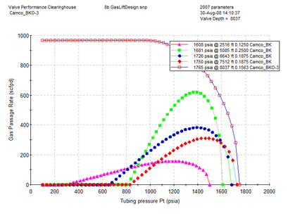
You can select a single valve to test by clicking on that valve and pressing the plot button. Under these conditions, you can test other reservoirs pressures. The next example shows what one valve looks like with all 3 methods.
