|
<< Click to Display Table of Contents >> Gas Lift Valve Design Tutorial |
  
|
|
<< Click to Display Table of Contents >> Gas Lift Valve Design Tutorial |
|
Objective: Determine Optimal gas injection volume and depth, space mandrels and size valve ports.

These are the steps:
| • | Open SNAP, go to File -> Open and Open example file c:\program files (x86)\snap\8aGLSURV.snp. |
| • |
| • | Page through each of the panels so you are familiar with the raw data going into the analysis. |
| • |
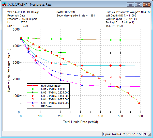
| • | Run the case and review the results. |
| • | Notice the depth sensitivity implies, "the deeper the better" , so go to the gas lift panel and place the injection point as low as physically possible (8900 ft TVD as a start). |
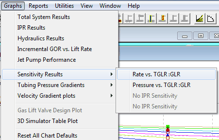
| • | After you have confirmed that lower is always better on depth of injection, go to the sensitivities panel and run a sensitivity on Gas Lift GLR. |
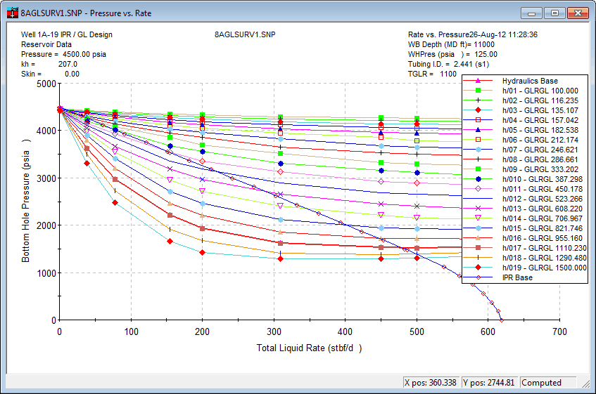
| • | What you see above shows that there is significant variance on lift based on GLR so plot the sensitivity graph. |
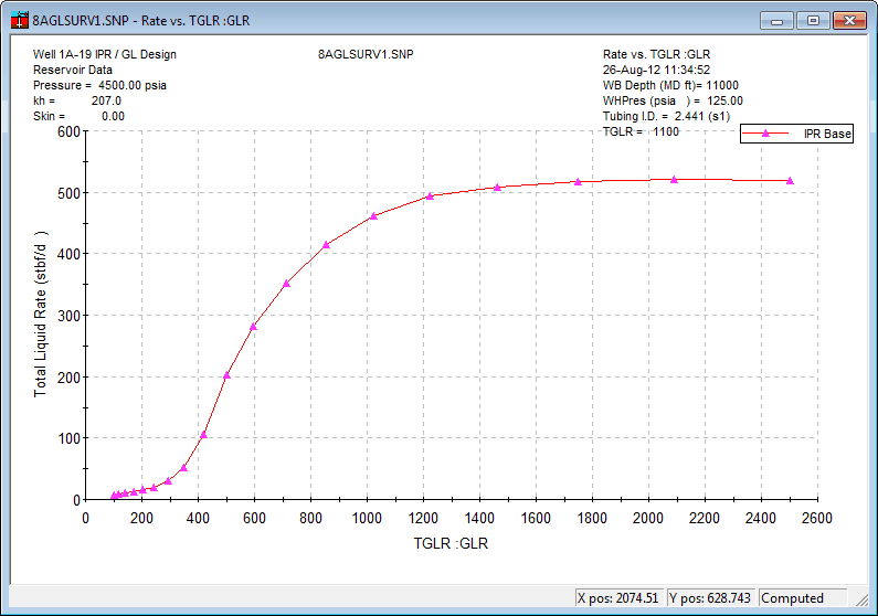
| • | This shows that the well only needs about 1200 glr before it starts overlifting (the oil rate does not increase as the GLR increases) so take that as a good starting point for the detailed gas lift design. |

| • | On the gas lift design page, you can estimate the potential liquid rate and required gas-lift injection pressure. For this case, it is reasonable to design the gas lift at at a TVD depth of 8900, an operating injection pressure above 1080 psia, and a flow rate of 500 BLPD. |

| • | Now we know what properties to design around, so go back to the General tab and change the gas lift to Gas lift Design (Check Gas Lift Design). |

| • | Page forward with the Next button until you hit the gas lift design page. |

| • | Enter your best estimates of design parameters here. Notice the Kick-off pressure is well above the operating pressure of 1082 determined on the prior step. This is because you will need some pressure drop to allow each valve to step down as the well kick's off. You can enter 500 BLPD or press the "import" button near the objective Liquid Rate to bring across as data from the prior solution. |
| • | The nodal plot indicates the well can produce 500 blpd but it may not be possible with your lift gas system unless you have enough lift pressue and lift gas rate to match the design. |

| • | If the default injection depth is not at the design lift point, adjust the single default valve to that depth.  |
| • | Press the apply button and see the case without any detailed valve data. |
| • |
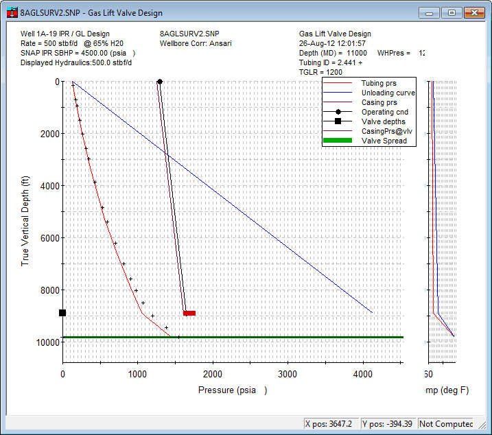
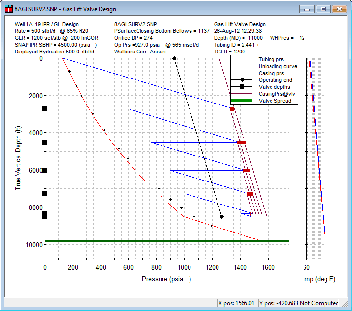
You have sufficient lift gas volume and pressure to lift to the design depth. Higher lift pressures can be used to lift greater volumes but those pressures will not require any unloading valves so let's assume that you only have 1250 psia available for now.
Notice the little crosses that indicate the results of a gas-lift survey. These are posted on the plot so that you can determine if your hydraulics are accurate at the conditions that the survey was run. Since there is a kink in this gradient data at about 8900 feet you may want to try to match the gradient data by lifting at that location. But once you change the rate or the GLR or the lift depth, you should no longer expect this survey to match your gradients so don't be upset if the crosses no longer match your gradient line.
| • | Close the panel and SAVE the Dataset as a new name. This is now a valve design dataset so it is worth creating a new dataset to reflect that. |
| • | Re-open the gas lift panel and turn to the Valve design Tab. Notice that there is one default valve at 8900 ft. This will be discarded once you ask for mandrels to be spaced. by pressing the Mandrel Spacing Utility button. |
![]()
| • | This utility will bring up another panel with some preferences concerning your design, including the maximum injection depth and design options. |

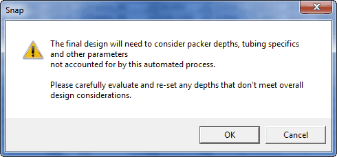
| • | When you push the "Do Spacing Line Design Method" button, you will see be notified that the design is approximate and should be independently reviewed accuracy and suitability. |
 |
| • | Once you close this warning, you will see the new spacing that the program has built, attempting to meet your constraints. It will have about 6 valves, BUT, the spacing is based on all the prior data you have provided as well as all the preferences that you have set up for your installation of the program. It is normal and expected to get slightly different results than shown here since each designer has different perspectives and preferences. |
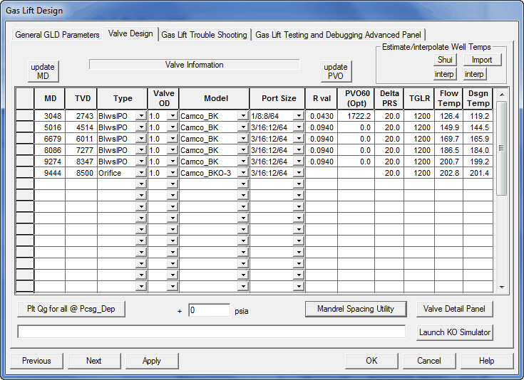
| • | Before looking at the design plot, it important to "post" the design Test-rack pressures to the case and re-"apply" that change. |
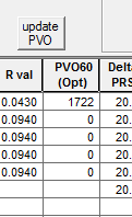 <<< BEFORE PRESSING "Update PVO" AFTER PRESSING >>>
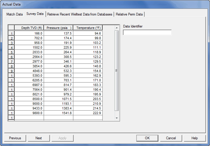
This Test rack data can be input if it is an existing well, or posted from the recommended design if a new installation is being designed.
| • | The design plot looks simple, but presentable. Notice there is 927 psia operating pressure listed in the header info. |
| • | Now turn back to the valve design tab and adjust the actual valves to match the ones you plan to buy. |
Adjust the port sizes such that the Gas-lift report shows that each valve is passing the required amount of gas at this location. In this case you will see that you may need to use 1.5" mandrels to pass enough gas to lift this well at the rates and volumes required!
| 1) | Make use of the gas lift Kick-off simulator to tune in required lift gas rates at each valve and the port size you will need at each valve. |

| 2) | Make sure the black operating condition line appears on the plot so that you are sure the orifice is passing the design amount. |
| 3) | Add mandrels to account for conditions that you have not anticipated and test all scenarios you can envision. Dummy off the mandrels you do not need. Press the interpolate temps and update MD buttons to make sure all the parts of the wellbore are at the correct gyro locations. |
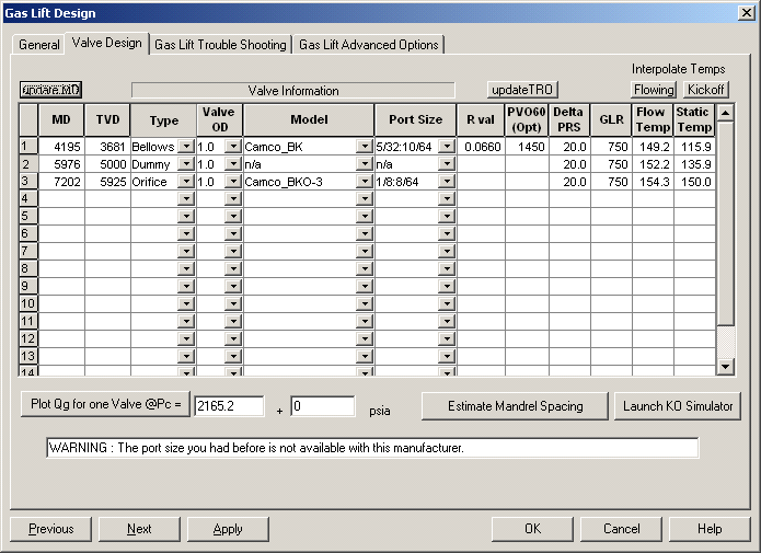
Even with all this work, this is a very simple valve design and there are still problems with it:
1) it is not possible to move enough gas through the top valve to get to the second location with a 1" mandrel, and
2) the orifice has the largest port possible in it so there is no option to up-size.
This technology is best used by experts who have years of experience in placing and designing valves, but we all have to start somewhere, so this short tutorial will give you an idea of the type of input required and the decisions that are made during the design process.