|
<< Click to Display Table of Contents >> Heat Transfer and Heat Balance Properties |
  
|
|
<< Click to Display Table of Contents >> Heat Transfer and Heat Balance Properties |
|
Heat Transfer and Heat Balance Properties
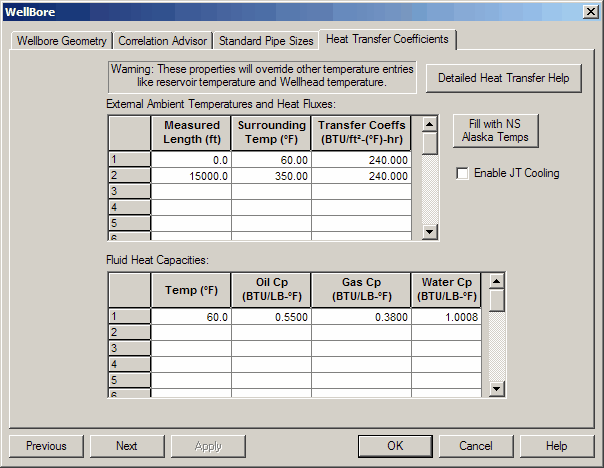
To Access:
Click WellBore
Under Temperature Options choose Rigorous Heat Transfer
Click Heat Transfer Coefficients
Excerpt from HeatTransfer.xls spreadsheet provided by ScandPower and originally built by Amoco.
This spreadsheet calculates the outside film coefficient for pipes for input into OLGA.
It also calculates the conduction analog of the convective heat loss in a well annulus.
It can also calculate the inside film coefficient for forced convection in a pipe.
There are a total of 8 sheets in this file:
a) Forced convection for water past a pipeline;
b) Forced convection for air past a pipeline;
c) Free convection for water;
d) Free convection for air;
e) General forced convection calculations;
f) General free convection calculations.
g) Well annulus equivalent conduction
h) Forced convection inside a pipe
Free and Forced Convection Outside Pipes
Values for the physical properties of water and air have been coded in for sheets a)-d). The
user must provide values for the physical properties in the final two sheets.
The user can only put in values for the input data on sheets a)-d). All other values are protected.
The user can modify any values by removing the protection from that sheet. The sheets are not
password protected. All input items are shown in red.
The spreadsheets allow the user to put in their values in either English or metric units. Please note
that the program does not convert units. The English and metric calculations are independent of
each other.
The program uses the equations for forced and free convection found in SPE 20903,
"Modelling the Performance of High-Pressure High-Temperature Wells" by A.C. Baker and M.Price.
Equations are:
Forced Convection:
Nu = (0.4*Re^0.5+.06*Re^0.67) Pr^0.4
Free Convection:
For Gr<1E9, Nu = 0.555*Ra^0.25
For Gr>1E9, Nu = 0.021*Ra^0.41
Well Annulus Calculations
OLGA's heat transfer models calculate convective heat transfer for the inside film in a pipe, and the
heat transfer to the surrounding. All other heat transfer is assumed to be by conduction. In a well,
there is frequently convective heat transfer in the annulus between the tubing and the casing. In
order to model the annulus heat transfer, it is necessary to convert the convective film coefficients
into an equivalent thermal conductivity for the annular fluid. This sheet calculates the equivalent
thermal conductivity for the annular fluid.
Forced Convection Inside A Pipe
This spreadsheet calculates the film coefficient for forced convection inside a pipe. It uses
standard single phase heat transfer methods. It assumes volumetrically averaged physical properties for a two
phase mixture. The method gives quick estimates of the film coefficients, and it is similar to the
methods used in most steady state simulators.
<<<<<<<<<<<<<<<<<< FORCED INSIDE >>>>>>>>>>>>>>>>>>>>>>>>>>>>>>>>>>>>
Laminar Flow:
Nu = 1.86*(Re*Pr*D/L)^0.33 (Laminar Flow for Re < 2100 and Re*Pr*D/L > 10)
(Set Nu = 3.7 if Re*Pr*D/L < 10)
Turbulent Flow (Turbulent Flow for Re > 6000 and Pr > 0.7)
Nu = 0.023*Re^0.8*Pr^0.33
Transition Flow (Transition Flow for 2100 < Re < 6000)
(Assuming Nu changes linearly from Laminar Nu to Turbulent Nu)
The physical properties of the gas and liquid are averaged using volumetric averages,
except for the specific heat, which is averaged based on the mass flux of each phase.
The mixture Re and Pr are used to calculate the heat transfer coefficient.
English |
Metric |
|
Superficial Gas Velocity |
1.00 ft/s |
0 m/s |
Superficial Liquid Velocity |
1.00 ft/s |
0.305 m/s |
Gas Density |
5.00 lbm/ft3 |
80.10 kg/m3 |
Liquid Density |
62.40 lbm/ft3 |
1000.00 kg/m3 |
Gas Viscosity |
0.015 cp |
0.000015 kg/m/s |
Liquid Viscosity |
400.00 cp |
0.400000 kg/m/s |
Gas Specific Heat |
0.60 BTU/lbm/degF |
2510.0 J/kg/degC |
Liquid Specific Heat |
1.00 BTU/lbm/degF |
4180.0 J/kg/degC |
Gas Thermal Conductivity |
0.031 BTU/hr/ft/degF |
0.0536 W/m/degC |
Liquid Thermal Conductivity |
0.083 BTU/hr/ft/degF |
0.144 W/m/degC |
Diameter |
12.000 inch |
0.305 m |
Length (for laminar flow only) |
11.000 mile |
16.000 km |
|
|
|
|
|
|
Mixture Properties: |
|
|
|
|
|
Velocity |
2.00 ft/s |
0.31 m/s |
Density |
33.70 lbm/ft3 |
1000.00 kg/m3 |
Viscosity |
200.01 cp |
0.400000 kg/m/s |
Specific Heat |
0.97 BTU/lbm/degF |
4180.0 J/kg/degC |
Thermal Conductivity |
0.057 BTU/hr/ft/degF |
0.1440 W/m/degC |
Re |
501 |
233 |
Pr |
8237.38 |
11611.11 |
Nu |
7.60 |
6.83 |
h |
0.43 BTU/hr/ft2/degF |
3.22 W/m/degC |