|
<< Click to Display Table of Contents >> Gas Lift Design Trouble Shooting |
  
|
|
<< Click to Display Table of Contents >> Gas Lift Design Trouble Shooting |
|
This panel is used to test an existing design and see what the predicted performance of the valve placements and settings. The program will implement whatever values are in the cells. It is valuable to determine if the design gas volume can be passed through the last valve or if it is likely tat the well is multi-point lifting. All of the cells in the output section are locked and can only be changed by changing the values in the upper part of this panel or in previous panels.
The following items may be edited on the GAS LIFT TROUBLE SHOOTING Panel:
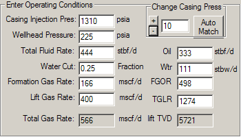
CASING INJECTION PRESSURE (psig): The surface casing pressure under operating conditions for the case to be calculated. The starting value is automatically imported from the previous panel. Clicking the AUTO MATCH BUTTON runs the calculation for current case and returns a casing pressure that matches case conditions. . If you wish to run a “what if” case for different surface casing pressures, type the new value into this field and click the APPLY BUTTON at the bottom of the panel. The program will re-run the calculations and update the output section of the panel.
WELLHEAD PRESSURE (psia): The flowing tubing pressure at the surface. The initial value is automatically imported from a previous panel. If you wish to run a “what if” case for different wellhead pressures, type the new value into this field and click the APPLY BUTTON at the bottom of the panel. The program will re-run the calculations and update the output section of the panel. This value can also be changed by clicking the “+/- Change Casing Press" buttons”. The default value for the +/- buttons is 10 psig, but another value can be typed into this field
TOTAL FLUID RATE (blpd): The total liquid flow rate for the case to be calculated. The initial value is automatically imported from a previous panel. If you wish to run a “what if” case for a different flow rate, type the new value into this field and click the APPLY BUTTON at the bottom of the panel. The program will re-run the calculations and update the output section of the panel. This field is linked to the WATER CUT, FORMATION GAS RATE, OIL, WATER, FGOR, and TGLR fields. Changing this value will automatically update the others.
WATER CUT (decimal fraction): The water cut flow rate for the case to be calculated. The initial value is automatically imported from a previous panel. If you wish to run a “what if” case for a different water cut, type the new value into this field and click the APPLY BUTTON at the bottom of the panel. The program will re-run the calculations and update the output section of the panel. This field is linked to the FORMATION GAS RATE, OIL, WATER, FGOR, and TGLR fields. Changing this value will automatically update the others.
FORMATION GAS RATE (mscfpd): The volume of formation gas produced for the case liquid rate and FGOR. The initial value is automatically imported from a previous panel. If you wish to run a “what if” case for a different formation gas rate, type the new value into this field and click the APPLY BUTTON at the bottom of the panel. The program will re-run the calculations and update the output section of the panel. This field is linked to the WATER CUT, OIL, WATER, FGOR, and TGLR fields. Changing this value will automatically update the others.
LIFT GAS RATE (mscfpd): The injected volume of lift gas for the case to be calculated. The initial value is automatically imported from a previous panel. If you wish to run a “what if” case for a different lift gas rates, type the new value into this field and click the APPLY BUTTON at the bottom of the panel. The program will re-run the calculations and update the output section of the panel. This field is linked to the TGLR field so that updating either one of them will automatically update the other.
OIL (bpd): The volume of oil produced for the case to be calculated. The initial value is automatically imported from a previous panel. If you wish to run a “what if” case for a different oil rate, type the new value into this field and click the APPLY BUTTON at the bottom of the panel. The program will re-run the calculations and update the output section of the panel. This field is linked to the TOTAL FLUID RATE, WATER CUT, FORMATION GAS RATE, WATER, FGOR, and TGLR fields. Changing this value automatically update the others.
WTR (bpd): The volume of water produced for the case to be calculated. The initial value is automatically imported from a previous panel. If you wish to run a “what if” case for a different water rate, type the new value into this field and click the APPLY BUTTON at the bottom of the panel. The program will re-run the calculations and update the output section of the panel. This field is linked to the TOTAL FLUID RATE, WATER CUT, FORMATION GAS RATE, OIL, FGOR, and TGLR fields. Changing this value will automatically update the others.
FGOR (scf/stb): The initial value is automatically imported from a previous panel. If you wish to run a “what if” case for a different FGOR, type the new value into this field and click the APPLY BUTTON at the bottom of the panel. The program will re-run the calculations and update the output section of the panel. This field is linked to the TOTAL FLUID RATE, WATER CUT, FORMATION GAS RATE, OIL, WATER, and TGLR fields. Changing this value will automatically update the others.
TGLR (scf/stb): Total gas liquid ratio including both formation and lift gas. The initial value is automatically imported from a previous panel. If you wish to run a “what if” case for a different TGLR, type the new value into this field and click the APPLY BUTTON at the bottom of the panel. The program will re-run the calculations and update the output section of the panel. This field is linked to the TOTAL FLUID RATE, WATER CUT, FORMATION GAS RATE, OIL, WATER, and FGOR fields. Changing this value will automatically update the others.
Trouble Shooting Grid Description
Gas lift GLTS compares the Tubing Pressure Gradient with the Operating Casing Injection Pressure to determine;
| • | If the lift point is at the orifice - volume of lift gas that will pass through the orifice |
| • | If the unloading valves are open or closed - volume of lift gas through each valve |
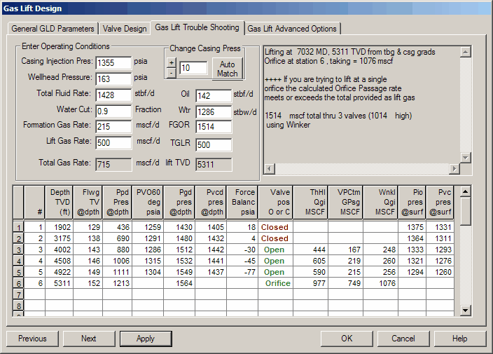
Depth TVD (ft) - The gas lift mandrel set depth, ft TVD.
Flwg TV @ depth - Flowing temperature of produced fluid at depth. Based on the surface FTT and either the Shui or Interpolation method to calculated wellbore temperature at depth.
Ppd Pres @ depth - Flowing production pressure in the tubing at depth. Based on surface FTP and tubing hydraulics, wellbore geometry, PVT properties, flow rate, gas lift rate, hydraulics correlation
PVO 60 deg psia - Test Rack Opening pressure of the gas lift valves installed in the well.
Pgd pres @depth - Casing pressure opposite the valve and Mandrel at the given conditions.
Pvcd pres @ depth – Dome pressure at depth where the gas lift valve is closed. Based on the flowing temperature of produced fluid at depth (Flwg TV) and the Test Rack Opening Pressures (PVO 60).
Force Balance psia - the pressure describing the degree to which a valve is open or closed.
| • | Difference between the operating Casing injection pressure at surface and the surface closing pressure (Pvc) of the gas lift valve. |
| • | A negative number indicates a valve is open, and a positive number indicates an closed valve. A small number means that eh valve is on the verge of opening or closing. |
.
Valve Pos Open or Closed – If the force balance indicates the valve is closed, the word Closed will appear in red. If it is open, the word open will appear.
ThHl Qgi MSCF – The gas passage rate predicted by the Thornhill Craver method under the conditions shown at that valve location
VPCtm Qgi MSCF – The gas passage rate predicted by the Valve Performance Clearinghouse (TM) method under the conditions shown at that valve location
Wnkl Qgi MSCF – The gas passage rate predicted by the Winkler method under the conditions shown at that valve location
Pio pres @ surf – Casing injection pressure to open valve at surface. Based on the pressure to open the valve at depth (Piod) less the weight of the column of lift gas.
Pvc pres @ surf – Casing injection pressure to close the valve at surface. Based on the dome pressure at depth where the gas lift valve is closed (Pvcd) less the weight of the column of lift gas.