|
<< Click to Display Table of Contents >> Fractured Well Model |
  
|
|
<< Click to Display Table of Contents >> Fractured Well Model |
|
Hydraulically Fractured Oil IPR
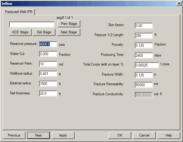
RESERVOIR PRESSURE (psia): The average reservoir pressure in the well's drainage area and can be obtained from pressure buildup analysis.
WATER CUT (frac): The fraction of the total liquid flow stream that is made up of water. In the results, fluid rate data is reported as TOTAL fluid which includes this water cut fraction.
RESERVOIR PERMEABILITY (md): The absolute (i.e., fluid independent) permeability averaged over the net thickness of the zone. These values are typically obtained from measurements on core samples using air as the fluid medium. Effective (i.e., fluid dependent) permeability estimates can be obtained from pressure transient analysis. These estimates can then be converted to absolute permeability values.
WELLBORE RADIUS (ft): The radius obtained from the caliper log, or the drill bit size when hole washout is not a problem. The Wellbore Radius Examples may be used as a guideline.
EXTERNAL RADIUS (ft): The distance between the well and the no-flow boundary created by off-setting wells in a developed pattern. It is equal to one half the square root of the well spacing: Rectangular drainage radius = 0.5 * ( 43560 * A ) where A is the spacing (acres.) Drainage Area Examples
NET THICKNESS (ft): The height or thickness of the zone believed to contribute flow. It is usually obtained from well log analysis and should be consistent with the average permeability specified.
SKIN FACTOR: A dimensionless number representing the near wellbore condition of damage or stimulation, where a positive factor indicates damage and a negative factor indicates stimulation. This factor is obtained from pressure transient analysis of drawdown or buildup data. It is important to remember that the completion effects are included in this number, i.e. horizontal wellbore, perforation density, gravel pack, etc..
FRACTURE 1/2 LENGTH: The distance from the wellbore to the tip of one of the fracture wings (ft). This number is part of the original design and can be estimated from pressure transient tests once the fracture is pumped. Typical 1/2 lengths range from 50-1000 ft.
POROSITY (fraction): The formation porosity is used in the fracture IPR as part of the storativity term. Lower porosities will result in lower rates.
PRODUCING TIME (days): The length of time the well has been on production with the current fracture in place. Since the fracture model is a transient model, the results depend on what time the rates and pressures are required. Short times will produce high rates and will fall into the linear model (tdxf < .016) while longer times give more traditional rates with the darcy or quadratic models. There may be a discontinuity between the two models due to independence of some parameters in the pseudo steady state model.
TOTAL COMPRESSIBILITY (1.e -6): The total system compressibility for use in the storativity terms in the model. Typical values are 20.0E-6 for oil systems and 500E-6 for gas systems. Input to the panel is just the first part of the value since the E-6 term is assumed. (I..E. for oil enter 20, for gas enter 500).
FRACTURE WIDTH: The fracture aperture in inches. This is part of the design or can be estimated from pressure transient tests. Typical values are 0.1 to 0.4 in.
FRACTURE PERMEABILITY (md):
FRACTURE CONDUCTIVITY (md): This is the permeability of the propped fracture and is primarily a function of the propant type and any degradation that it has experienced. Typical values are given in the gravel permeability table Gravel Permeability Examples
*Note: This Help Update will be completed at a later time.