|
<< Click to Display Table of Contents >> Babu & Odeh Horizontal Model |
  
|
|
<< Click to Display Table of Contents >> Babu & Odeh Horizontal Model |
|
Babu and Odeh Horizontal Model
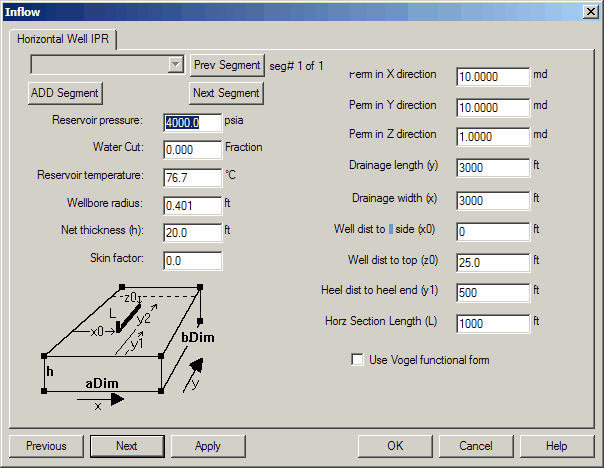
RESERVOIR PRESSURE (psia): The average reservoir pressure in the well's drainage area and can be obtained from pressure buildup analysis.
WATER CUT: The fraction of the total liquid flow stream that is made up of water. In the results, fluid rate data is reported as TOTAL fluid, which includes this water cut fraction.
RESERVOIR TEMPERATURE (°C): The bottomhole temperature at the reservoir depth. It is obtained from direct measurement or using the local geothermal gradient and the prevailing surface temperature
WELLBORE RADIUS (ft): The radius obtained from the caliper log, or the drill bit size when hole washout is not a problem. The Wellbore Radius Examples may be used as a guideline.
NET THICKNESS (ft): The height or thickness of the zone believed to contribute flow. It is usually obtained from well log analysis and should be consistent with the average permeability specified.
SKIN FACTOR: A dimensionless number representing the near wellbore condition of damage or stimulation, where a positive factor indicates damage and a negative factor indicates stimulation. This factor is obtained from pressure transient analysis of drawdown or buildup data. It is important to remember that the completion effects are included in this number, i.e. horizontal wellbore, perforation density, gravel pack, etc..
PERMEABILITY (md): The absolute (i.e., fluid independent) permeability averaged over the net thickness of the zone. These values are typically obtained from measurements on core samples using air as the fluid medium. Effective (i.e., fluid dependent) permeability estimates can be obtained from pressure transient analysis. These estimates can then be converted to absolute permeability values.
X direction: This is the permeability PERPENDICULAR to the axis of the well.
Y direction: This is the permeability ALONG the axis of the well
Z direction: This is the vertical permeability (perpendicular to the bedding plane).
DRAINAGE LENGTH (ft): The length of the approximate rectangular area drained along the horizontal well.
DRAINAGE WIDTH (ft): The width of the approximate rectangular area drained across the well path.
WELL DIST TO || SIDE x0(ft): Labeled “x0’” on the figure. The shift of the well axis off from the side running along with the horizontal well path. E.G. If the well is drilled right along the edge of a fault on one side, this number would be close to zero. If it is in the center of the drainage rectangle, this number would be ½ of the DRAINAGE WIDTH.
WELL DIST TO TOP z0(ft): Labeled “z0’” on the figure. The shift of the well axis down from the top running along with the horizontal well path. E.G. If the well is drilled along the top of a formation (or bottom), this number would be close to zero. If it is in the center of the drainage rectangle, this number would be ½ of the NET HEIGHT. Since gravity effects are not considered in this model, the distance from the top or bottom can be given, whichever is smaller.
HEEL DIST TO HEEL END y1(ft): Labeled “y1’” on the figure. The shift of the well axis horizontal well path from the heel of the drainage area to the heel of the well. E.G. If the well is drilled into the drainage area such that it enters at the edge of the drainage and traverses straight away from that drainage boundary, the number would be close to zero. If it is in the center of the drainage rectangle, this number would be ½ of (DRAINAGE LENGTH – WELL LENGTH).
HORIZONTAL SECTION LENGTH z0(ft): Labeled “L’” on the figure. This is simply the DRILLED length of the horizontal wellbore assuming that it penetrates uniform formation from heel to tow. In reality this number may be significantly different since different qualities of reservoir will be encountered along the horizontal section. This is the most common “knob” used to match actual well performance but little technical justification exists for this practice.
*Note: This help file update will be completed at a later time.