|
<< Click to Display Table of Contents >> Gas Lift Setup Report Detail |
  
|
|
<< Click to Display Table of Contents >> Gas Lift Setup Report Detail |
|
Gas Lift Setup reports are intended to be a formal documents, customized by each Gas Lift user to simplify the process of providing valve running details to the field.
This 4 page report consists of:
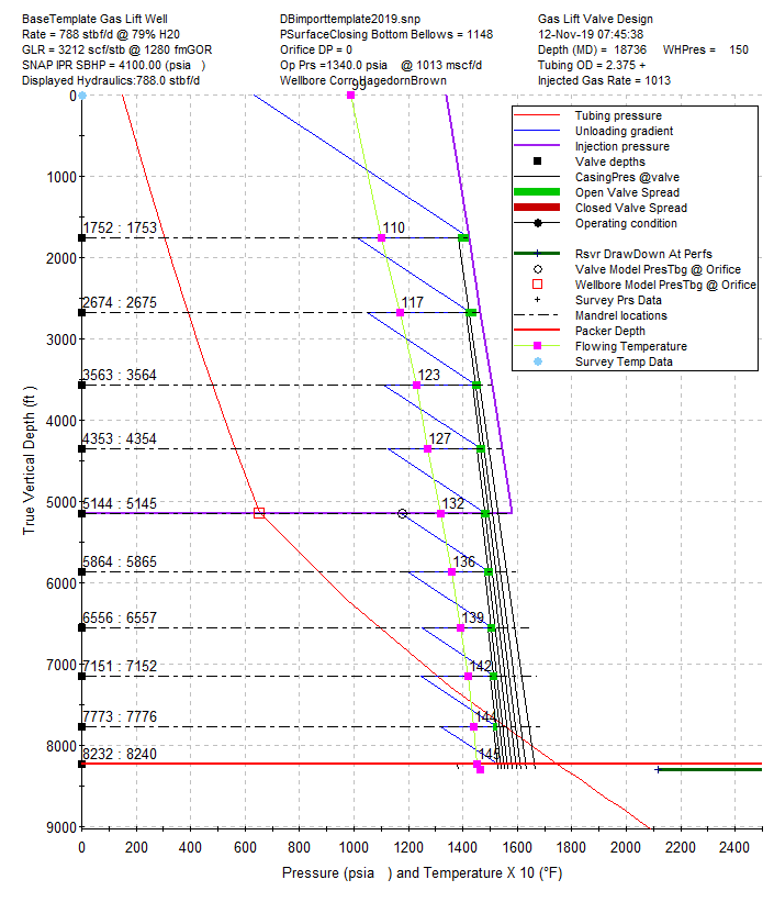
| 1. | a design plot, |
| 2. | a standard SNAP one page design report (not including warnings or errors), |
| 3. | a slickline procedure for running the valves and the data used to generate the design, |
| 4. | a Recommended Unloading procedure using values specific to the well and some values that are embedded in the GLVSETUPTEMPLATE.RTF file. |
Below is a sample report:
_
Page 1
-----------------------------------------------------------------------------------
Engineer : Nations
Dataset : DBimporttemplate2019.snp
Title : BaseTemplate Gas Lift Well
-----------------------------------------------------------------------------------
Important Note: Review page 3 of this report for actual and potential problems.
Nations Solution Rate: 787 stbf/ Pvc Bottom Bellows: 1148
GL Design Press: 1340 Solution fbhp: 2121 psia Operating Pressure: 1340
Wellhead Pressure: 150 Flwg Wh Temp (Twh): 99 Casing DP: 384
SNAP IPR function Top Valve Flwg Temp: 110 Orifice DP: N/A
Static BHP(Pws): 4100 Static BH Temp: 146 KO Gas Gradient : 0.0466
SNAP 2.699 11/11/2019 Tubing Size: 1.875 Operating Gas Grd: 0.0454
11/12/19 07:49:16 Design GL Rate: 1013 Watercut: 78.8 %
Model: HagedornBrown Unloading Gradient: 0.450 Formation GOR: 1280
Design QO: 167 stbf/d Design QW: 620 stbf/d Design QFmGas: 214 mscf/d
Rn Sta Depth Depth Valve Valve Valve Port Valve Valve Flwg
Or # TVD MD OD Type Model Size Ap/Ab Ppef Tmp
10 1 1752 1753 1.0 Bellows Wfd_R-1 0.1875 0.7000 0.1038 110
9 2 2674 2675 1.0 Bellows Wfd_R-1 0.1875 0.7000 0.1038 117
8 3 3563 3564 1.0 Bellows Wfd_R-1 0.1875 0.7000 0.1038 123
7 4 4353 4354 1.0 Bellows Wfd_R-1 0.1875 0.7000 0.1038 127
6 5 5144 5145 1.0 Bellows Wfd_R-1 0.1875 0.7000 0.1038 132
5 6 5864 5865 1.0 Bellows Wfd_R-1 0.1875 0.7000 0.1038 136
4 7 6556 6557 1.0 Bellows Wfd_R-1 0.1875 0.7000 0.1038 139
3 8 7151 7152 1.0 Bellows Wfd_R-1 0.1875 0.7000 0.1038 142
2 9 7773 7776 1.0 Bellows Wfd_R-1 0.1875 0.7000 0.1038 144
1 10 8232 8240 1.0 Orifice Wfd_RDDK-1 0.2500 0.0000 0.0000 145
Rn Sta Ppd Pwf Qliq* TGLR Qgi(req) Qgi(VPC) Qgi(ThH) Qgi(Wnk) Ptro60 Ptro
Or # Prs psia stbf/d scf/b mscf mscf mscf mscf calc Instld
10 1 302 3870 200 200 -14 1287 982 1118 1379 1145
9 2 390 3493 271 200 -19 1287 986 1120 1389 1135
8 3 480 3153 419 200 -30 1246 961 1090 1394 1125
7 4 559 2812 554 200 -40 1250 966 1094 1400 1115
6 5 655 2121 787 1557 1012 1329 990 1105 1403 1105
5 6 863 2218 758 200 -54 1202 934 1057 1405 1095
4 7 1089 1949 837 200 -60 1148 893 1013 1409 1090
3 8 1304 1682 906 200 -65 1164 906 1026 1409 1080
2 9 1555 1519 945 200 -67 1056 824 936 1412 1075
1 10 1749 2121 787 3212 3005 0 0 0
Rn Sta Pgd GLD GLD GLD Pvc Ppd-Pmin
Or # Prs Piod Pvcd PpTran Ct Pio Psc DP psia
10 1 1422 1422 1383 1013 0.903 1344 1308 20 711
9 2 1465 1450 1412 1049 0.891 1325 1288 20 660
8 3 1506 1467 1434 1111 0.881 1301 1268 20 631
7 4 1543 1484 1451 1127 0.874 1281 1248 20 568
6 5 1580 1498 1468 1173 0.866 1258 1228 20 518
5 6 1613 1511 1481 1197 0.860 1237 1208 20 334
4 7 1646 1519 1493 1249 0.855 1213 1188 20 160
3 8 1673 1528 1501 1246 0.850 1194 1168 20 -58
2 9 1702 1530 1510 1320 0.847 1167 1148 20 -235
1 10 1724 1380 -628
Slick Line Procedure
Run the following gas lift design based on the HagedornBrown hydraulic correlation, 788 BLPD, 79% Water Cut, 1013 Mscfd lift gas, 1280 FGOR, kickoff pressure of 1340.0 psi, and Wfd_R-1 valves.
Surf. Surf. TRO
MD Valve Valve Port Open Close Press
GLM (RKB) Size Name Size Press Press 60° F
1 1753 1" Wfd_R-1 3/16" 1344 1308 1379
2 2675 1" Wfd_R-1 3/16" 1325 1288 1389
3 3564 1" Wfd_R-1 3/16" 1301 1268 1394
4 4354 1" Wfd_R-1 3/16" 1281 1248 1400
5 5145 1" Wfd_R-1 3/16" 1258 1228 1403
6 5865 1" Wfd_R-1 3/16" 1237 1208 1405
7 6557 1" Wfd_R-1 3/16" 1213 1188 1409
8 7152 1" Wfd_R-1 3/16" 1194 1168 1409
9 7776 1" Wfd_R-1 3/16" 1167 1148 1412
10 8240 1" Wfd_RDDK-1 1/4" ------ Orifice ------
Recommended Unloading Procedure
| 1) | Slowly work the production choke open to reduce the tubing pressure to common line pressure. |
| 2) | Start lift gas injection at 50-150 Mscfd. |
| 3) | Monitor the casing annulus pressure to target a 50-100 psi increase every 30 minutes (50-100 psi/30 min) |
| 4) | Increase lift gas injection to a maximum of 200 Mscfd. |
| 5) | At 200 Mscfd the calculated time to drop the annulus fluid level to the 1st gas lift valve is 2.8 hrs. |
| 6) | After unloading to the 1st gas lift valve, increase the gas lift rate to 2/3 of the design rate. (2/3) ( 1013 Mscfd) = 675 Mscfd. |
| 7) | The annulus fluid level will drop past each unloading valve and stabilize lift gas injection at the orifice within 12-18 hours depending on the number of valves. |
| 8) | Check that the annulus casing pressure is less than the closing pressure of the bottom gas lift valve = 1248 psig. |
| 9) | Increase the lift gas rate to the design rate of 1013 Mscfd. |
| 10) | The stabilized operating annulus casing pressure is 1340 psig. |
| 11) | Contact Tom Nations at tom@nationsconsultinginc.com (281) 301-9999 |
| ✍ | For any questions or issues with unloading the well. |
| ✍ | If the operating annulus casing pressure is 150 psi above or below design. |