|
<< Click to Display Table of Contents >> Flowline |
  
|
|
<< Click to Display Table of Contents >> Flowline |
|
Flowline
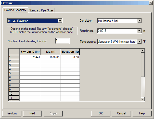
The following items may be edited on the Flowline Geometry Panel:
The total length of the flowline is input using segments to describe the flowline profile, changes in pipe diameter, and nonlinear temperature profiles. The flowline geometry is described starting at the separator and working toward the wellhead. The total number of flowline and well segments cannot exceed 20.
FLOWLINE GEOMETRY OPTIONS:
Measured Length vs. Elevation
Measured Length vs. Angle
Elevation vs. Angle
FLOWLINE INSIDE DIAMETER (in): The inside diameter of the flowline.
FLOWLINE MEASURED LENGTH (ft): This is the CUMULATIVE measured pipe length from the separator. Each segment accumulates on the next, so a 100 foot section attached to a 1500 section which is attached to the separator would be 1600 feet measured length.
FLOWLINE ELEVATION (ft): The CUMULATIVE net elevation in feet above (negative) or below (positive) the separator level. This is also relative to the separator inlet, NOT the end of the prior segment. For a separator uphill from the wellhead, the elevation of the last segment should be positive (standard is positive downward like in the wellbore).
FLOWLINE ANGLE (degrees): The angle measured CLOCKWISE from the horizontal looking from the separator to the wellhead. For horizontal flowline, the angle is 0. For a separator uphill from the wellhead, the angle would be positive. These angles are NOT cumulative.
SEGMENT TEMPERATURE (F): Temperature at the end of each flowline segment. The program uses the wellhead and separator temperature and calculates a linear temperature gradient. However, this option can be used to specify a nonlinear temperature profile in the flowline by specifying additional segments and temperatures.
FLOWLINE ROUGHNESS (in): The absolute roughness, in inches, of the pipe segment under consideration. It is used to calculate the friction factor. The Crane handbook (technical paper 410) is a good source of pipe roughness data. Here appear recommended values.